The Fenton oxidation method can serve as a pretreatment process before wastewater biochemical treatment, as well as an advanced treatment process following wastewater biochemical treatment.
The Fenton oxidation method is primarily suitable for treating wastewater containing hard-to-degrade organic substances, such as wastewater from the paper industry, dyeing and finishing industry, coal chemical industry, petrochemical industry, fine chemical industry, fermentation industry, landfill leachate, and wastewater from centralized wastewater treatment plants in industrial parks.
What is the Principle of the Fenton Reaction?
In 1893, chemist Fenton HJ discovered that a mixture of hydrogen peroxide (H2O2) and ferrous ions (Fe2+) exhibited strong oxidizing properties, capable of oxidizing many known organic compounds such as carboxylic acids, alcohols, and esters to inorganic states, with remarkable oxidation effects. However, this oxidizing agent was not given much attention for over half a century afterward due to its strong oxidizing capacity. Entering the 1970s, the Fenton reagent found its place in environmental chemistry, demonstrating a high capability to remove hard-to-degrade organic pollutants. The Fenton reagent has been widely applied in the treatment of various wastewater, including dyeing wastewater, oily wastewater, phenolic wastewater, coking wastewater, nitrobenzene wastewater, and diphenylamine wastewater, among others. When Fenton discovered the Fenton reagent, it was not clear what oxidant produced by the reaction between hydrogen peroxide and ferrous ions had such strong oxidizing power. More than twenty years later, it was hypothesized that the reaction might produce hydroxyl radicals. Otherwise, the oxidizing power would not be so strong. Therefore, a widely cited chemical reaction equation was adopted to describe the chemical reaction occurring with the Fenton reagent:
Fe2++H2O2→Fe3++OH−+OH⋅
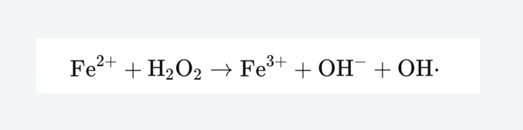
The Fenton oxidation method operates under acidic conditions, where H2O2 in the presence of Fe2+ generates hydroxyl radicals (·OH) with strong oxidizing capability, initiating a chain reaction of other reactive oxygen species to degrade organic substances. The oxidation process is a chain reaction, with the production of ·OH marking the start of the chain, while other reactive oxygen species and reaction intermediates form the chain’s nodes. As these reactive oxygen species are consumed, the reaction chain terminates. The reaction mechanism is relatively complex, with these reactive oxygen species attacking organic molecules and mineralizing them into inorganic substances such as CO2 and H2O. Thus, the Fenton oxidation method has become one of the important advanced oxidation technologies.
Water Quality Requirements for Fenton Reaction
The influent water for the Fenton oxidation process should meet the following conditions:
- Pollutants that can produce toxic and harmful gases under acidic conditions (such as sulfide ions, cyanide ions, etc.) should not enter the Fenton oxidation process unit.
- The content of suspended solids in the influent should be less than 200 mg/L.
- The concentration of Cl-, H2PO4-, HCO3-, oils, and other inorganic ions or pollutants that affect the Fenton oxidation reaction in the influent should be controlled. Their limiting concentrations should be determined based on experimental results.
When the influent water does not meet the conditions for the Fenton oxidation process:
Appropriate pretreatment measures should be taken based on the water quality of the influent:
- When the Fenton oxidation method is used for pretreatment before biochemical treatment, coarse and fine screens, sand settling tanks, sedimentation tanks, or coagulation sedimentation tanks can be set up to remove easily removable pollutants such as floatables, sand, and suspended solids. Coagulation sedimentation and/or filtration processes should be set up for pretreatment when the Fenton oxidation method is used for advanced wastewater treatment.
- When the influent has a high concentration of dissolved phosphates, lime should be added to remove part of the dissolved phosphates through coagulation sedimentation.
- When the influent contains oils, an oil separator should be set up to remove the oil.
- When the influent contains sulfide ions, chemical precipitation or chemical oxidation methods should be used for removal; when the influent contains cyanide ions, chemical oxidation methods should be used for removal.
- When the influent contains other substances that affect the Fenton oxidation reaction, appropriate removal measures should be taken based on the water quality to eliminate their impact on the Fenton oxidation reaction.
- When the Fenton oxidation method is used for pretreatment before biochemical treatment, and if there is a significant variation in the water quality and quantity of the influent, an equalization tank should be set up before the Fenton oxidation process.

Key Determinants of the Fenton Reaction
Temperature
Temperature is one of the significant factors affecting the Fenton reaction. Generally, the rate of chemical reactions increases with temperature, and the Fenton reaction is no exception. An increase in temperature accelerates the generation of ·OH radicals, facilitating their reaction with organic matter, improving oxidation effects, and enhancing the removal rate of COD. However, for complex reaction systems like the Fenton reagent, an increase in temperature not only accelerates the forward reaction but also the side reactions. A higher temperature can also speed up the decomposition of H2O2 into O2 and H2O, which is unfavorable for generating ·OH radicals. The optimal temperature for the Fenton reaction varies with different types of industrial wastewater. For treating polyacrylamide aqueous solutions, the temperature is controlled between 30°C to 50°C. Studies on the treatment of rubber-washing wastewater found the optimal temperature to be 85°C. For treating trichlorophenol, temperatures below 60°C benefit the reaction, whereas temperatures above 60°C are not.
pH
Generally, the Fenton reaction occurs under acidic conditions. In neutral or alkaline environments, Fe2+ cannot catalyze the oxidation of H2O2 to produce ·OH radicals and iron hydroxide precipitates, losing its catalytic ability. When the concentration of H+ in the solution is too high, Fe3+ cannot be efficiently reduced back to Fe2+, hindering the catalytic reaction. Numerous studies have shown that the Fenton reagent has a strong oxidation capacity under acidic conditions, especially when the pH is between 3 and 5. At this pH range, the degradation rate of organic substances is fast and capable of degrading within a few minutes. The reaction rate constant for organic substances is directly proportional to the initial concentrations of Fe2+ and hydrogen peroxide. Therefore, in engineering applications of the Fenton process, it is recommended to adjust the wastewater to a pH of 2 to 4, with the theoretical optimum around 3.5.
Organic Substrates
The dosage of Fenton’s reagent and its oxidation effects vary with different types of wastewater. This variation is due to the different types of organic substances in various wastewater. For alcohols (such as glycerol) and carbohydrates, the action of hydroxyl radicals leads to dehydrogenation reactions followed by the breaking of C-C bonds. In the case of large carbohydrate molecules, hydroxyl radicals cause the glycosidic bonds within the sugar molecule chains to break, resulting in the degradation into smaller molecules. For water-soluble polymers and ethylenic compounds, hydroxyl radicals lead to the breaking of C=C bonds.
Moreover, hydroxyl radicals can open the rings of aromatic compounds, forming aliphatic compounds, thereby eliminating or reducing the biotoxicity of this type of wastewater and improving its biodegradability. In the case of dyes, hydroxyl radicals can open the unsaturated bonds of functional groups within the dyes, leading to oxidative decomposition, which achieves decolorization and reduces COD. Experiments using Fenton’s reagent to degrade chitosan have shown that the medium’s pH is between 3 and 5. The molar ratio of polysaccharide, H2O2, and catalyst ranges from 240:12 to 24:1 to 2; the Fenton reaction can break the glycosidic bonds within the chitosan molecule chain, thus generating small molecular products.
Dosage of Hydrogen Peroxide and Catalyst
Determining the dosage of reagents and their cost-effectiveness is crucial in the Fenton process for wastewater treatment. An increase in the dosage of H2O2 can improve the removal rate of wastewater COD, but beyond a certain point, the removal rate of COD begins to decline. This is because, in the Fenton reaction, an increase in H2O2 dosage leads to an increase in the production of ·OH, which raises the COD removal rate. However, when the concentration of H2O2 is too high, hydrogen peroxide undergoes decomposition without generating hydroxyl radicals. The situation with the catalyst dosage is similar to that of hydrogen peroxide. Generally, increasing the amount of Fe2+ increases the COD removal rate of wastewater. However, the COD removal rate declines when Fe2+ is increased to a certain level. This decline occurs because, at low concentrations of Fe2+, an increase in Fe2+ concentration leads to a rise in ·OH produced by H2O2. Still, at high concentrations of Fe2+, it can cause ineffective decomposition of H2O2, releasing O2 instead.
Fenton Process Operation and Design
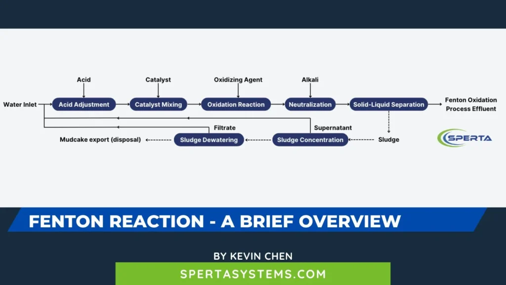
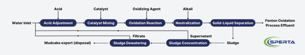
The wastewater treatment process flow of the Fenton oxidation method mainly includes acid adjustment, catalyst mixing, oxidation reaction, neutralization, solid-liquid separation, reagent dosing, and sludge treatment systems. A schematic diagram of the process flow is provided in the figure.
Acid Adjustment
The pH of the wastewater should be adjusted by adding concentrated or dilute sulfuric acid based on the optimal pH value conditions of the oxidation reaction tank, ideally controlled between 3.0 and 4.0.
Acid adjustment tanks should use hydraulic, mechanical, or air stirring, with a mixing time of no less than 2 minutes.
Concentrated or dilute sulfuric acid should be added using a metering pump, with an online pH control instrument or other automatic control systems to adjust the dosing amount.
Catalyst Mixing
The catalyst, such as ferrous sulfate, is mixed in the mixing tank, which should use hydraulic stirring, mechanical stirring, or air stirring, with a mixing time of no less than 2 minutes. The mass percentage concentration of the ferrous sulfate solution should be less than 30%, and it should be dosed quantitatively using a metering pump.
Oxidation Reaction
Hydrogen peroxide solution should be added to complete the oxidation reaction in the oxidation reaction tank, which can be a completely mixed type or plug flow type, with the completely mixed type having no less than two stages connected by overflow or perforated walls.
The type of oxidation reaction tank should be determined based on factors such as the scale of wastewater treatment, land area, and cost-effectiveness. When using a tower type, an up-flow reactor is preferred, and the tower’s steel structure should be made of stainless steel 316L with a glass flake anticorrosive coating. The tower reactor includes a Fenton reagent mixing area, water distribution area, and reaction area. The mixing area’s mixing speed gradient G value should not be less than 500 s^-1, the water distribution area should distribute water evenly, with an outlet flow rate of 1.0 m/s to 1.5 m/s, and the return ratio should not be less than 100%. The height-to-diameter ratio of the tower reactor should be between 1.0 and 5.0, with a height not exceeding 15 m.
The effective volume of the oxidation reaction tank can be calculated as follows:
𝑉=𝑄∙𝑇

Where:
- ( V ) — Effective volume of the tank, m³;
- ( Q ) — Design water volume, m³/h;
- ( T ) — Hydraulic retention time, h.
The effective area of the oxidation reaction tank can be calculated as follows:
𝐹= 𝑉/𝐻

Where:
- ( F ) — Effective area of the tank, m²;
- ( H ) — Effective tank depth, m, ideally 2.5 m to 6.0 m for completely mixed type.
The hydraulic retention time of the oxidation reaction pool should be determined through experiments based on the influent water quality, composition, and effluent requirements. The hydraulic retention time for pretreatment should be 2.0h to 8.0h; for advanced treatment, it should be 2.0 h to 6.0h.
Mixing can use hydraulic, mechanical, or air stirring to ensure uniform mixing and prevent short-circuiting and dead zones.
Experiments should determine the dosage and dosing ratio of reagents in the Fenton oxidation reaction. In the absence of experimental data, the dosing ratio c (H2O2, mg/L): COD (mg/L) should be 1:1 to 2:1; c (H2O2, mg/L): c (Fe2+, mg/L) should be 1:1 to 10:1.
Neutralization
The neutralization pool adjusts the pH value to neutral by adding alkali solutions, preferably using sodium hydroxide or sodium carbonate solutions, and not calcium hydroxide solutions. When the effluent from the Fenton oxidation method is directly discharged, the pH value should be adjusted to meet the requirements for solid-liquid separation and discharge; when the effluent enters subsequent treatment processes, the pH value should be adjusted to meet the requirements for solid-liquid separation and subsequent treatment processes.
The neutralization pool can use hydraulic stirring, mechanical stirring, or air stirring, with a mixing time of no less than 2 minutes.
When air stirring is not used in the oxidation reaction and neutralization processes, an air-stirring degassing tank should be set up, with a hydraulic retention time of no less than 15 minutes and a gas-water ratio of no less than 5:1.
Solid-Liquid Separation
Solid-liquid separation can be achieved through sedimentation or flotation. If the separation effect is poor, coagulants or flocculants can be added, preferably using polyaluminium chloride (PAC) at a dosage of 100 mg/L to 200 mg/L; flocculants should preferably be polyacrylamide (PAM) at a dosage of 3 mg/L to 5 mg/L. The type and dosing ratio of reagents should be determined by experiments when possible.
Reagent Dosing
The dosage of Fenton’s reagent, acid-base reagents, coagulants, and flocculants should be determined based on the characteristics of the wastewater and after experimentation.
The dosing of Fenton’s reagent and flocculants should be done using metering pumps and equipped with flow meters. Fenton’s reagent and flocculant dosing system should include storage, preparation, transportation, metering, and dosing facilities (spare).
When using hydraulic, mechanical, or air stirring for mixing reagents, the stirring speed gradient G value should be controlled between 1000 s^-1 and 500 s^-1. When using these chemical or coagulation methods, the stirring speed gradient G value should be controlled between 70 s^-1 and 50 s^-1, decreasing in stages.
Reagent Preparation
a) The dissolution and dilution methods for reagents (such as ferrous sulfate, sodium hydroxide, PAC, and PAM) should be determined based on the dosing amount and reagent properties. Dissolution and dilution should preferably use mechanical stirring, but hydraulic or air stirring can also be used.
b) The concentration of the solution should be chosen based on different solubilities and freezing points, ensuring the sulfuric acid concentration keeps the freezing point below the lowest winter temperature (see Table 1 for sulfuric acid freezing points); ferrous sulfate solution concentration should be prepared at a mass percentage concentration of ≤30%, and at lower temperatures, it should be prepared at ≤20%; hydrogen peroxide mass percentage concentration should be ≤30%; liquid alkali concentration should be ≤30%. Suppose the alkalinity of the water used for preparing reagents causes ferrous sulfate to crystallize. In that case, a suitable amount of sulfuric acid can be added during dissolution to reduce the precipitation of ferrous sulfate crystals in the dissolution and dosing tanks.
The table below shows the freezing points of sulfuric acid at different mass fractions (0.1 MPa)
| Mass Fraction (%) | 0 | 12.5 | 25 | 37.5 | 50 | 62.5 | 75 | 87.5 | 98 |
| Freezing Point (℃) | 0 | -8 | -27 | -70 | -36 | -29 | -40 | -14 | 6 |
c) The water pressure for hydraulic preparation should be greater than 0.2 MPa.
d) Compressed air preparation can be used for reagent preparation in wastewater treatment plants (stations) with large water volumes, with aeration intensity controlled between 3 L/(m²·s) and 5 L/(m²·s).
e) Sulfuric acid solutions should be ready-made to avoid dilution and preparation within the wastewater treatment plant. If ready-made supplies are unavailable and on-site preparation is necessary, consider the corrosiveness and exothermic nature of the dissolution process, using specialized equipment for preparation.
f) Hydrogen peroxide storage devices should be kept away from heat sources and protected from direct sunlight.
Calculation of Reagent Solution and Solution Tank Volumes
The volume of the solution tank can be calculated as follows:
𝑊 1 =(0.2~0.3)𝑊 2

Where:
- W1 — Volume of the solution tank, m³;
- W2 — Volume of the dissolution tank, m³.
The volume of the dissolution tank can be calculated as follows:
𝑊2= (2400 × 𝑎 × 𝑄)/(100000 × 𝑐 × 𝑛) = (𝑎× 𝑄)/(417 × 𝑐 × 𝑛)
Where:
- a — Maximum dosage of the reagent, calculated as anhydrous product, mg/L;
- Q — Design water volume, m³/h;
- c — Solution concentration, %;
- n — The number of daily preparations should be determined based on the dosage of reagents and preparation conditions and should generally not exceed 3 times per day.
Equipment and Material Selection
Main Structure
The main structure of the pools can be made of reinforced concrete or steel structure. Reinforced concrete pools are recommended for larger treatment scales, while steel structure tanks can be used for smaller scales.
The bodies of each unit and the materials, equipment, and connecting pipes should have the appropriate resistance to acid-base corrosion and antioxidation corrosion. The inner walls of reinforced concrete pools can be coated with epoxy resin fiberglass for corrosion protection. In contrast, the inner walls of steel tanks can be made of 316L stainless steel or coated with a glass flake for corrosion protection. The inner walls of the dissolution and solution tanks in the reagent dosing system can be covered with epoxy fiberglass, diabase, acid-resistant cement mortar with ceramic tiles, or PVC sheets, depending on the chemicals’ corrosiveness. When the substances are not strongly corrosive, acid-resistant cement mortar can be used.
Equipment and pipes in the reagent dosing system should take appropriate insulation or heat insulation measures based on the nature of the chemicals.
Pumps and Valves
Wastewater lift pumps and the flow components of the oxidation reaction pool circulation pumps should be resistant to acid-base corrosion and oxidation, preferably made of 316L stainless steel.
Pumps in the reagent dosing system, such as chemical dosing pumps, should also be made of corrosion-resistant materials. For concentrated sulfuric acid solution, dosing pump flow components can be made of PTFE or cast iron; for hydrogen peroxide solution, 316L stainless steel; for ferrous sulfate solution, 316L stainless steel, polypropylene, or PVC; for sodium hydroxide solution, 304 stainless steel. Valve flow components in the reagent dosing system should have linings matching the corresponding lift and dosing pumps.
Mechanical Mixers
The power and speed of mechanical mixers (such as frame mixers, paddle mixers, etc.) should be selected based on process design requirements, preferably using variable speed mixers. The underwater parts of mechanical mixers should be made of 316L stainless steel or fiberglass.
Piping
Wastewater conveyance pipes should be made of 316L stainless steel, polyethylene, polypropylene, or PVC materials for pipes and fittings.
For conveying concentrated sulfuric acid (98%), PTFE pipes or other pipes resistant to concentrated sulfuric acid corrosion and their corresponding fittings should be used. The hydrogen peroxide solution should be conveyed using 316L stainless steel pipes and fittings. Other chemical conveyance pipes should be made of polyethylene, polypropylene, or PVC materials for pipes and fittings. Chemical conveyance pipes should be equipped with the necessary filters to prevent clogging of metering pumps and pipelines.
Sludge Calculation and Disposal
The amount of sludge produced is mainly related to the volume of water, the concentration of suspended solids, types of organic pollutants, and the dosage of chemicals. Due to the variability in wastewater quality, the amount of sludge produced can differ significantly, and it is advisable to determine the sludge production through multiple experiments. When experimental conditions are not available, the dry sludge production can be estimated using the following formula:
TS=B×(S+K1F+K2A+P)×Q×10−6

Where:
- TS — Total amount of dry sludge, t/d;
- S — Concentration of suspended solids removed by the Fenton oxidation method, mg/L;
- K1 — Coefficient for the conversion of ferrous salts to sludge, taken as 1.9, the conversion coefficient from Fe2+ to Fe(OH)3;
- F — Dosage of ferrous salts, calculated as Fe2+, mg/L;
- K2 — Coefficient for the conversion of coagulants to sludge in the coagulation stage, if using aluminum salts, taken as 1.53, the conversion coefficient from Al2O3 to Al(OH)3;
- A — Dosage of coagulants in the coagulation stage, if using aluminum salts, calculated as Al2O3, mg/L;
- P — Dosage of flocculants (usually PAM) in the coagulation stage, mg/L;
- Q — Design water volume, m³/d;
- B — Safety factor, taken as 1.1 to 1.2.
Before sludge dewatering, chemical conditioning should be applied, and the type and dosage of chemicals should be determined based on experiments or by referring to data from similar types of sludge dewatering processes.
The selection of sludge dewatering equipment should be based on the properties of the sludge, the amount of sludge produced, and dewatering requirements. The moisture content of the dewatered sludge should meet the requirements for sludge treatment and disposal.
Sludge separated by the solid-liquid separation system should not be recirculated back into the biological treatment system. Dewatered sludge should be disposed of harmlessly according to relevant national regulations. Sludge listed in the “National Hazardous Waste List” or identified as hazardous waste should be stored and disposed of according to relevant regulations, while other sludges should be stored and disposed of appropriately, in accordance with local conditions and regulations.
The information above is a brief overview of Fenton reaction. If you still have related questions about wastewater treatment, please feel free to contact SPERTA.
Shanghai SPERTA Environmental Technology Co., Ltd. has specialized in producing water treatment products for many years. The company has MBR membrane technology, a complete technical team, and pre-sales and after-sales service. If you have any needs, please feel free to contact us.