Last Updated on January 6, 2026 by Kevin Chen
In MBR (membrane bioreactor) system design, membrane area is a key parameter that determines system stability, water production capacity, and membrane lifespan. Properly sizing the membrane area requires starting from the treatment flow and considering membrane type, effective filtration area, and operating conditions. Today, let’s take a deep look into the design objectives, key parameters, calculation methods, and practical engineering applications for membrane area design.
What Determines the Membrane Area?
The core objective of membrane area design is to ensure the system can reliably meet the treatment flow (system capacity) requirements.
Based on treatment flow: The daily flow directly determines the system’s required water production capacity. Design must guarantee sufficient output under normal and peak load conditions.
Ensuring long-term stable operation: A membrane area that is too small leads to a high design flux, faster TMP increase, and accelerated fouling. Too large a membrane area wastes investment and increases footprint and aeration costs.
Supporting design optimization and economic efficiency: Starting from treatment flow allows a balanced design of membrane quantity, flux, and aeration, reducing operating costs.
Thus, the treatment flow (capacity) is the foundation of membrane area design and the starting point of the MBR system design process.
Key Parameters for MBR Membrane Area Design
Before we calculate the required membrane area, we need to consider the following key parameters:
- Design flux (LMH)
Flux determines the water production per square meter of membrane; unit: LMH (liters per m2 per hour). We must balance short-term production targets with long-term membrane stability. Operating at higher flux can increase output, but it also accelerates the rise in TMP. - Effective filtration area vs. nominal membrane area
Nominal area is the theoretical area provided by different MBR membrane manufacturers. In practice, only a portion participates in stable filtration due to supports, aeration, flow patterns, and fouling. Effective filtration area is the basis for flux and TMP control, guiding membrane quantity and layout.
Further reading: 👉👉 How to Calculate MBR Membrane Surface Area? - Membrane module characteristics
Hollow fiber and flat sheet membranes have different structures and different calculations. Fiber length or sheet length, diameter, and packing density directly impact effective filtration area. - Water quality and sludge characteristics
High MLSS, COD, or suspended solids increase fouling risk, requiring a larger effective area to maintain flux. Sludge properties affect aeration and fiber-cleaning efficiency, thereby impacting the effective membrane filtration area. - Operating safety margin
We also need to consider the flow fluctuations, peak loads, and system aging. If we provide a safety margin in design, it can reduce the risk of TMP rise, extend membrane lifespan, and ensure stable operation under peak conditions.
What Is Design Flux in MBR Systems?
As mentioned in the previous section, design flux (LMH) defines the hourly water production per square meter of membrane. Selecting an appropriate design flux ensures stable operation, extends membrane service life, and helps optimize both system footprint and overall investment. Recommended flux by water type:
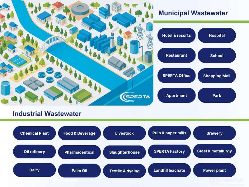
Municipal wastewater (low suspended solids, low organic loading)
Recommended design flux: 15–25 LMH
With relatively stable influent conditions and a lower fouling risk, a slightly higher flux can be adopted to reduce the required membrane area and overall capital investment.
Industrial wastewater (high suspended solids, high COD/BOD)
Recommended design flux: 8–15 LMH
Complex water quality and higher fouling potential require a lower design flux to control TMP rise and protect membrane lifespan.
High-strength wastewater (e.g., landfill leachate)
Recommended design flux: 6–8 LMH
Severe water-quality fluctuations and a high fouling risk demand strict flux control. Additional membrane area and optimized cleaning strategies are often necessary to ensure stable operation.
Notes:
- Flux selection must reflect actual water quality and operational experience.
- High flux reduces membrane area and footprint but increases TMP and cleaning frequency.
- Low flux prolongs membrane life, reduces energy and chemical consumption, but increases investment and footprint.
How to Calculate the Required Membrane Area Based on Treatment Capacity?
Calculation Formula:
Required MBR area (m²) = Target Flow(L/d) / Design Flux(L/m²/h) / Operating Hour per day(h)
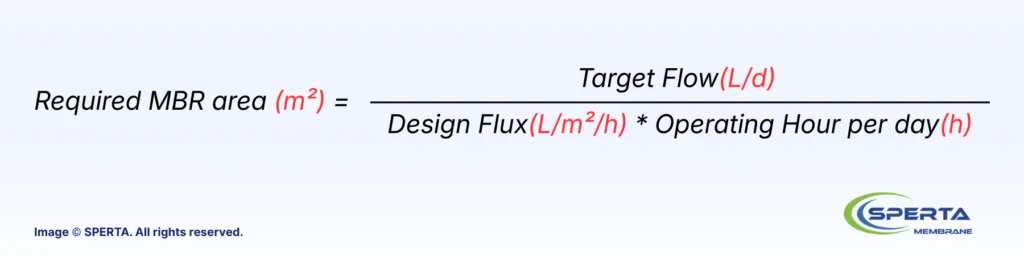
Parameter explanation:
- Target Flow (L/d): Daily design flow, the total wastewater the system must treat.
- Design Flux (L/m²/h): Water produced in liters per square meter of membrane per hour. Must be selected based on water quality characteristics (e.g., domestic sewage, industrial wastewater, or landfill leachate).
- Operating Hours per Day (h): Daily system operation hours, typically around 20 hours at full load of the suction pump.
Calculation steps:
- Confirm the daily treatment capacity.
- Select a suitable design flux based on influent water type and quality.
- Set the actual daily operating hours.
- Apply the formula to calculate the required membrane area.
Example:
An industrial park MBR system has:
Daily flow: 1000 m³/d = 1,000,000 L/d
Water quality: industrial wastewater, design flux: 12 L/m²/h
Operating hours: 20 h/d
Required membrane area = 1,000,000 / 12 / 20 ≈ 4,167m²
This system requires at least approximately 4167 m² of effective membrane area to meet the design flow.
Notes:
The above calculations are based on typical design assumptions and reference flux values. In practice, the design flux should be adjusted based on actual influent characteristics, including COD, suspended solids, sludge concentration (MLSS), DO, temperature, etc.
Engineering Application: SPERTA Case Example
To illustrate how membrane area requirements vary across different project scales and water qualities, the following examples show typical sizing logic used in engineering practice.
Domestic Wastewater Project: 1000 m³/d, design flux 18 LMH, safety margin 15%. Calculated design area: 1,000,000 / 18 / 20 * 1.15% ≈ 3,195m².
Textile Wastewater Project: 2,500 m3/d, design flux 15 LMH, safety margin 20%. Calculated design area: 2,500,000 / 15 / 20 * 1.2% ≈ 10,000m².
SPERTA Tips:
- Include a 10–20% margin to account for flow fluctuations or water quality changes.
- Adjust calculations for different membrane types and manufacturers based on effective filtration area.
- For high-pollution water, such as leachate, reduce flux or increase membrane area to control TMP and maintain membrane lifespan.
- Operating temperature, sludge concentration (MLSS), and dissolved oxygen (DO), etc., can also influence membrane performance and fouling behavior. These factors should be evaluated during design, and manufacturer consultation or pilot data is strongly recommended before finalizing flux and membrane area.
Conclusion
Proper MBR membrane area design is based on treatment capacity, effective filtration area, and appropriate design flux. Using an effective filtration area helps control TMP, ensure stable operation, and extend membrane lifespan.
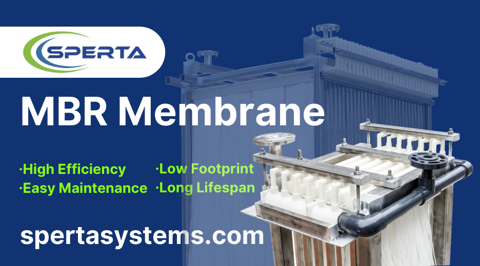
SPERTA is a professional manufacturer specializing in MBR membrane modules and system applications. If you need support in determining the required membrane area for your project, feel free to contact SPERTA for technical consultation and engineering assistance.