Pumps are the devices used for transporting or pressurizing liquids and are indispensable in the wastewater treatment industry. Therefore, calculating the pump head is crucial. An insufficient head means the water cannot be pumped up, while an excessive head wastes energy. This article will guide you through the methods to calculate the pump head.
What Does Pump Head Mean?
The pump head refers to the height at which a pump can raise water from its suction inlet to its highest delivery point. Represented by the symbol H, its unit is meters. For centrifugal pumps, the head is based on the impeller centerline. It consists of two parts: the vertical height from the pump impeller centerline to the water source surface, known as the suction head, and the vertical height from the pump impeller centerline to the water surface of the discharge pool, known as the discharge head. Thus, the total pump head = suction head + discharge head. It’s important to note that the head indicated on the pump’s nameplate refers to the head generated by the pump itself, excluding the head loss due to friction in the pipes. This should not be overlooked when selecting a pump, or the water may not be pumped effectively.

How to Calculate the Head of the Pump?
The relationship between pump head and power is insignificant, it largely depends on the impeller’s diameter and the number of impellers (G number). Pumps of the same power can have vastly different heads and flow rates. There is no standard formula for calculating head, the operating conditions and the pump model chosen determine it. For example, considering the suction pressure, a pump outlet of 1MPa (10kg/cm²) corresponds to a head of about 100 meters. The change in head directly affects the pump’s flow rate. Typically, the total head needs to account for the resistance loss in the entire pipeline and pump.
Centrifugal pumps’ flow rate decreases as the head increases, and vice versa. A high head reduces flow, increasing power consumption and potentially overheating and damaging the motor if overloaded.
What Is the Formula for Calculating Pump Head?
The pump head represents the height at which the pump can raise water, a key performance parameter also known as the pressure head. It can be expressed as the increase in fluid’s pressure head, kinetic head, and potential head, i.e.,
H=(p2-p1)/ρg+(v2²-v1²)/2g+z2-z1
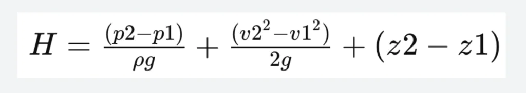
Where H is the head (m)
ρ1,ρ2: the liquid pressures at the pump inlet and outlet (Pa)
v1,v2: the fluid velocities at the pump inlet and outlet (m/s)
z1,z2: the distances between two pressure measuring points (m);
ρ: the liquid density (kg/m³);
g: the acceleration due to gravity (m/s²).
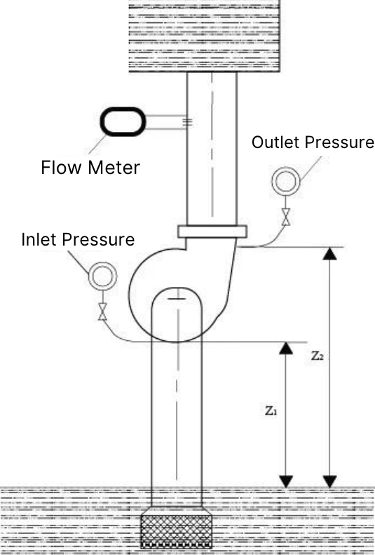
The pump head can be determined experimentally by installing a vacuum gauge at the inlet and a pressure gauge at the outlet.
Example:
Calculate the head of a centrifugal pump pumping water at 20°C with a flow rate of 10L/s. The vacuum gauge at the inlet reads 0.031Mpa, and the pressure gauge at the outlet reads 0.126Mpa (gauge pressure). The vertical distance between the two gauges is 80mm, with inlet diameter d1=80mm and outlet diameter d2=60mm
H=(p2-p1)/ρg+(v2²-v1²)/2g+z2-z1
p1/ρg=−3.16m
p2/ρg=12.8m
v1 =4qv/πd1² = 4×10×10-3/π×802×10-6 = 1.99m/s
v1 =4qv/πd2² = 4×10×10-3/π×602×10-6 = 3.54m/s
H = 0.08+(12.8+3.16) (3.542-1.992)/2×9.81 = 16.5m
The pump’s head is 16.5m.
Quick Estimation Considering Other Pipeline Conditions
In actual operation, pumps do not just pump vertically; they navigate bends, tees, and horizontal distances, all contributing to losses. Thus, a more precise estimation of the pump head is required.
- One elbow ≈ 0.5m loss in pump head
- 10m horizontal distance ≈ 1m loss in pump head
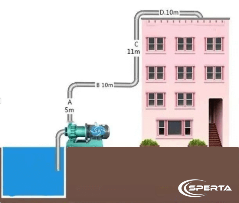
Using the diagram as an example, with known dimensions: A height of 5m, B length of 10m, C height of 11m, D length of 10m, and three elbows. The actual operational head would be calculated as follows:
A + elbow + B + elbow + C + elbow + D
5m + 0.5m + 1m + 0.5m + 11m + 0.5m + 1m = 19.5m
Conclusion
The above is the information about the calculation of the head of the pump. If you still have related questions, please feel free to contact SPERTA.
Shanghai SPERTA Environmental Technology Co., Ltd. has specialized in producing water treatment products for many years. The company has its own MBR membrane technology, a complete technical team, and pre-sales and after-sales service. If you have any needs, please feel free to contact us.